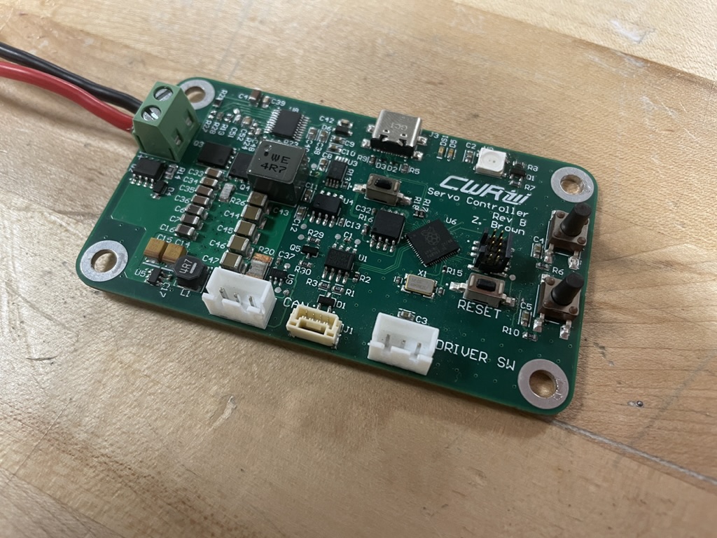
Servo Controller is the PCBA on the 2023 Baja SAE car that was responsible for actuating our four-wheel drive system. In essence, it is a high current buck regulator supervised by a Raspberry Pi RP2040. Reality is always more complicated than that though, so let’s look at some specifics.
The Mechanical System

On CWRU Motorsports’ four-wheel drive vehicles, we use a dog-clutch to connect our rear and front driveline together through a chain. To actuate this dog clutch, we use a pretty beefy hobby servo motor from Savöx. This motor provides us up to 972.1oz-in of torque at about 450 degrees/second, which we then put into a fork to slide the dog in and out of the sprocket. This means our actuation time is extremely fast, and our system engages and disengages smoothly compared to other potential systems. It has been rock-solid since we started using it, but it does come with a few drawbacks.
If only it were that easy.
A motor that provides as much torque as our servo at the speed it does comes with some serious power requirements. In the case of our motor, running at a voltage of 7.4V, we have a stall current of 9.2A! How the 22ga conductors coming out of the servo were picked for that current I have no idea. An additional compounding factor is the fact that the bus voltage of our car sits at around 14V, so we need to not only provide that much current, but also do it through a regulator that can provide at least 70W of power. Being the overachiever I am, I shot for a factor of safety of about 1.5 on the output current, so 15A at 7.4V, or about 115W.
How we did it before.
In the past, we used an Arduino Nano connected to a COTS Pololu buck regulator in a 3D printed enclosure. This was more expensive than Servo Controller, larger, and less capable since you had to plug in the module and edit the actual code to change the endstops of the servo. We also had this module fail on us at a competition in Arizona, which meant I was left in the hotel soldering while the team went out to dinner.
The new kid on the block.
The regulator is obviously the keystone of this board, so let’s start there. I used TI’s Webench power designer to develop a basic synchronous buck topology regulator that I could start with. From there, I did some tweaking based on component availability, as well as performance goals I wanted to meet. Here’s the design I ended up with:

It is a pretty standard implementation of the LM25116 from TI, but with a few additions. First, the RP2040 has control over it’s enable pin, meaning it is the last thing to be brought up in terms of the boards hardware according to the firmware. Second, there is a current shunt on the output of the regulator, in between it and the servo. This is so that the RP2040 can actively monitor the servo current consumption and detect either a stall condition, or ensure that the servo isn’t going to go into thermal runaway (which we had issues with in the past).
Layout
I laid out Servo Controller on a 4 layer PCB with a stackup of sig | gnd | 3V3 | sig. This stackup isn’t ideal in terms of EMI for larger designs, but I kept pretty much every component except for some passives on the top layer where they were as close to ground as possible.

you can see the regulator on the left size of the design, with the polygon pours for the input, switching node, and output. I made sure to be liberal with stiching vias to ground to minimize the impedance to ground of the filtering capacitors, as well as generally improve signal integrity on the board.
Cyphal
The last thing I’d like to touch on for Servo Controller is its ability to communicate over CAN to the rest of the car via the Cyphal protocol. Servo Controller specifically is able to publish it’s servo current consumption, switch state, and status over the network, while subscribing to a message to turn four-wheel drive on and off. As far as I know, it is also the first RP2040 to implement a Cyphal/CAN bootloader via Kocherga, Zubax Robotics’ open-source embedded bootloader for Cyphal/DroneCAN.
Lessons learned
Servo Controller taught me mostly about designing decently big buck regulators, and especially how to debug them. I had a lot of issues with Rev A simply because I didn’t fully understand what was going on. I learned a ton about bootstrapping NFETs, compensation networks, and even higher frequency board layout. Servo Controller was also my first experience with the RP2040, which I found to be pretty enjoyable all in all. There were some things I felt were either missing or hiding behind CMSIS/register level code, but for the most part it was pretty painless.